From Friday, April 19th (11:00 PM CDT) through Saturday, April 20th (2:00 PM CDT), 2024, ni.com will undergo system upgrades that may result in temporary service interruption.
We appreciate your patience as we improve our online experience.
From Friday, April 19th (11:00 PM CDT) through Saturday, April 20th (2:00 PM CDT), 2024, ni.com will undergo system upgrades that may result in temporary service interruption.
We appreciate your patience as we improve our online experience.
NI’s industry-leading power electronics are used by OEMs, top tier suppliers, and research labs worldwide. Our selection of cyclers addresses a wide range of conditions to meet your evolving needs.
We provide modular, high-performance, easy-to-use, safe, and reliable solutions for industries like automotive, aerospace, and defense—and we are committed to supporting the product lifecycle from R&D, high-volume manufacturing/production, end of life, and remanufacturing.
NI’s DC power electronics portfolio provides the speed and performance to accurately emulate today’s technologies and tomorrow’s innovations for all battery chemistries, fuel cells, supercapacitors, and energy storage systems. Modular battery test systems address the increasing power requirements of battery modules and packs used in the electric vehicle and renewable energy storage industries.
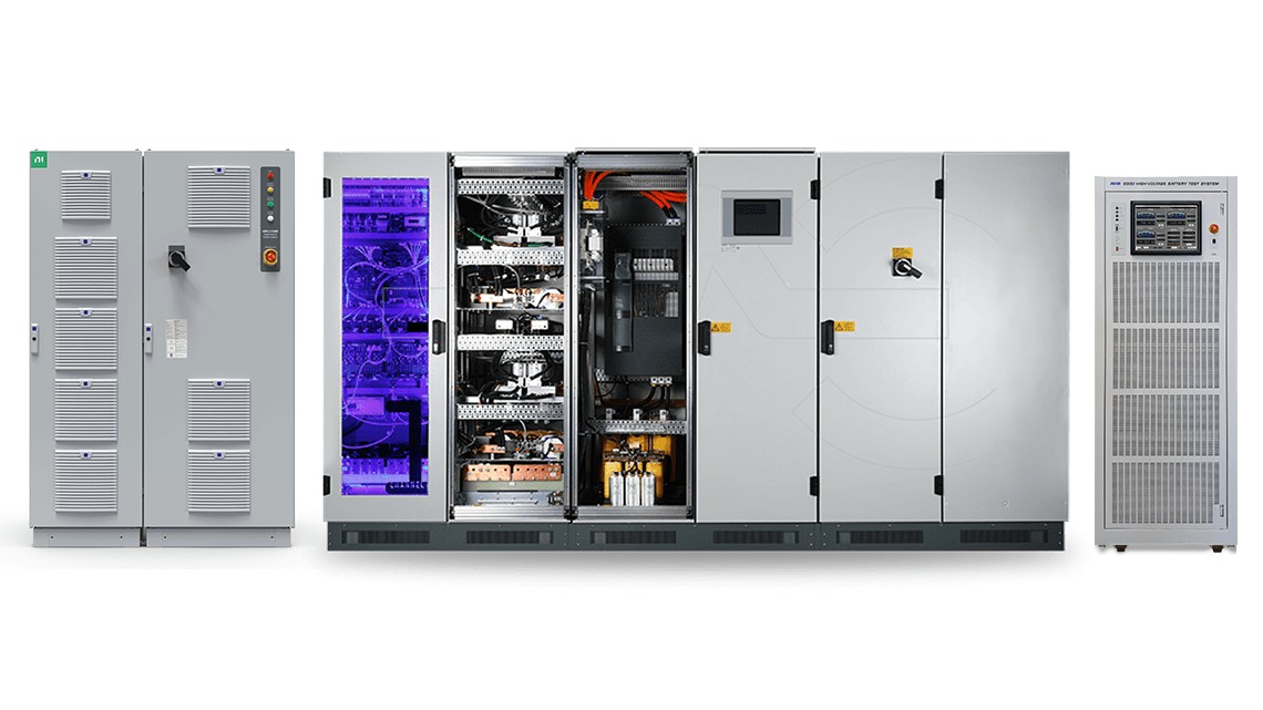
Battery test equipment includes high- and medium-voltage DC power test systems. NI battery test systems can be used as battery cyclers, regenerative bidirectional DC sources, regenerative DC loads, high-power DC sources, or battery/DC emulators.
The High-Voltage DC Battery Pack Cycler and Emulator offers modular, regenerative battery pack test capabilities with a power range spanning from 100 kW to 2.4 MW. This versatile range caters specifically to EV battery pack testing needs, ensuring comprehensive and scalable solutions for validating and testing battery packs across various power capacities.
Designed for EV battery module testing, NI’s Mid-Voltage DC Battery Module Cycler and Emulator serves as a multifunction solution for battery cycling and emulation needs. This system is ideal for low- to medium-power applications in research, validation, and production labs.
NI's AC loads and sources provide versatile capabilities for custom test systems. These high-performance AC power electronics offer flexibility and ease of use, with features tailored to meet the diverse test needs of the electric vehicle, aerospace, renewable energy, and energy storage industries. They’re critical for simulating real-world electrification conditions, enabling faster testing and reducing energy costs by emulating bidirectional power flows in transportation and renewable energy systems.
Battery Test Software, Enerchron™, and PAtools™, are innovative software solutions designed to revolutionize high-power and automated testing of EV components. These industry-leading tools provide seamless, efficient, and highly accurate test execution and data analysis, ensuring optimal performance and reliability in the world of battery cell, module and pack testing, and EV component evaluation.
Battery Test Software powered by PAtools revolutionizes your battery lab by harnessing NI’s software-defined lab methodology. This innovative approach future-proofs your battery testing procedures, offering automated and streamlined workflows alongside advanced data management and analysis capabilities.
PAtools software is a comprehensive test development environment for EV test systems offering hardware integration, streamlined workflow interfaces, pre-built tests and analysis, and real-time reliability.